

Industrial production lines
Centralized supply, starting and protection arranged around the motor list and process sequence.
Motor & Automation Control · Centralized Motor Control
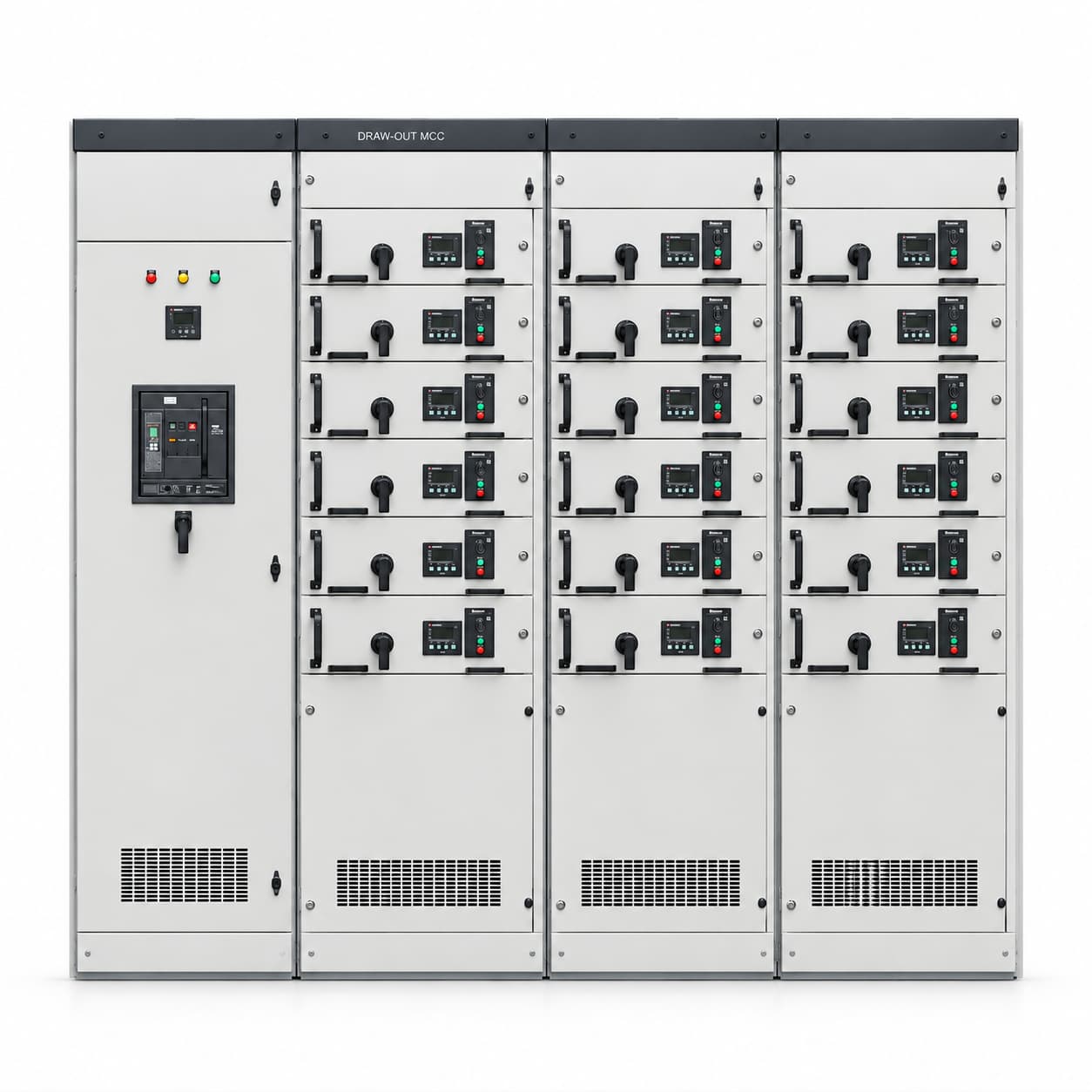
MCC cabinets provide centralized power supply, starting, control and protection for multiple motors. Incoming supply, feeders, motor control, metering and communications are configured to the motor list and process requirements.
Choose empty enclosures or assembled equipment. Frames, doors, functional units and mechanical accessories follow the agreed list. Empty supply does not include busbars, electrical components, internal wiring or control programs by default; assembled scope follows the confirmed drawings and configuration list.
These uses help assess suitability; they are not completed project references.
Centralized supply, starting and protection arranged around the motor list and process sequence.
Motor circuits and control logic defined by pump ratings, simultaneous operation and standby needs.
Starting or speed-control methods selected to fan loads and process requirements.
Control scheme confirmed around drive motors, start / stop sequences and interface needs.
Options follow manual pages 18–19. Current ratings, functional units, starting methods, protection and control configuration require confirmation against loads, structure and environment; options are not all included by default or suitable in every combination.
| Item | Listed options / configuration | To confirm for the project |
|---|---|---|
| Main-circuit voltage | AC 380 / 400 / 415 / 440 / 460 / 480 V | Other voltages are project-specific. |
| Operating frequency | 50 / 60 Hz | Other frequencies are project-specific. |
| Control supply | DC 24 V / AC 110 V / AC 220 V | Confirmed to the control scheme; other voltages are specified separately. |
| Installation | Floor-standing, single cabinet / lineup | Defined by project layout. |
| Incoming & busbar rated current | Project-specific | Defined by motor loads, simultaneous operation and the distribution scheme. |
| Motor & circuit count | Defined by motor list and control requirements | Confirm motor count, control circuits and spare-circuit needs separately. |
| Power & current per circuit | Defined by motor nameplate and loads | Confirm rated current, load characteristics and operating conditions. |
| Starting & speed control | Direct-on-line / star-delta / soft start / VFD control | Selected to motor and process needs; not all methods are included by default. |
| Functional units | Fixed / withdrawable (drawer-type) | Unit specifications, interfaces and interlocks are project-specific. |
| Degree of protection | IP30 / IP40 / IP54 | Confirm suitable structure and environment for the project; other ratings require assessment. |
| Enclosure steel thickness | 1.5 / 2.0 mm | Other thicknesses are project-specific; frame, doors and mounting plates are confirmed separately. |
| Material & surface treatment | Cold-rolled steel / galvanized steel / stainless steel | Material, finish and colour follow project requirements. |
| Protection configuration | Short-circuit, overload, phase-loss and other protection | Selected to the motor and protection scheme. |
| Operation & control | Local / remote, manual / automatic | Confirmed to the control logic; PLC, HMI, communications and metering are optional. |
| Dimensions & cable entry | Width × height × depth, in mm | Lineup, cable entry / exit and maintenance space follow the confirmed drawings. |
Withdrawable construction does not imply live insertion / removal or maintenance without shutdown. Operation, isolation and maintenance conditions follow the confirmed scheme.
Final parameters, configuration and scope of supply are subject to the confirmed drawings and order agreement.
Mechanical enclosure and functional-unit construction defined for the project.
Enclosure with the agreed components and internal wiring.
Control programs, PLC/HMI programming, site commissioning, external wiring and complete system integration are not included by default. Work scope, interfaces and deliverables require a separate agreement.
Provide motor loads together with process-control needs to define circuits, construction and supply scope.
Use Additional Requirements for the motor list, starting methods, simultaneous operation and control interfaces. After preparing the draft, attach motor schedules, electrical drawings and control descriptions in your email app.
Request an MCC QuoteIncoming, assembly and outgoing checks follow the confirmed product configuration and order scope.
Required documents, submission stages and any witness or special inspection requirements are agreed before the order.
MCC is a motor-control functional category; GCS and MNS are structural series. A project may use either structure for MCC functions, so the categories are not mutually exclusive. Units, interfaces and interlocks require confirmation.
No. Direct-on-line, star-delta, soft starting and VFD control are selected to motor and process needs. PLC, HMI, communications and metering are optional.
No such capability is claimed here. Unit construction, interlocks and isolation conditions require project confirmation; maintenance follows the confirmed shutdown, isolation and operating requirements.
No. Scope, interfaces and deliverables for control programs, PLC/HMI programming, site commissioning and complete system integration require a separate agreement.
The quote button preselects MCC. Enter motor, load and control requirements, prepare the draft, then attach motor schedules and drawings in your email app and review before sending.
Final parameters, configuration and scope of supply are subject to the confirmed drawings and order agreement.