

Industrial distribution
Incoming, feeder, bus-coupler and measurement circuits organized around the factory LV system diagram.
LV Main Distribution · Modular Structure
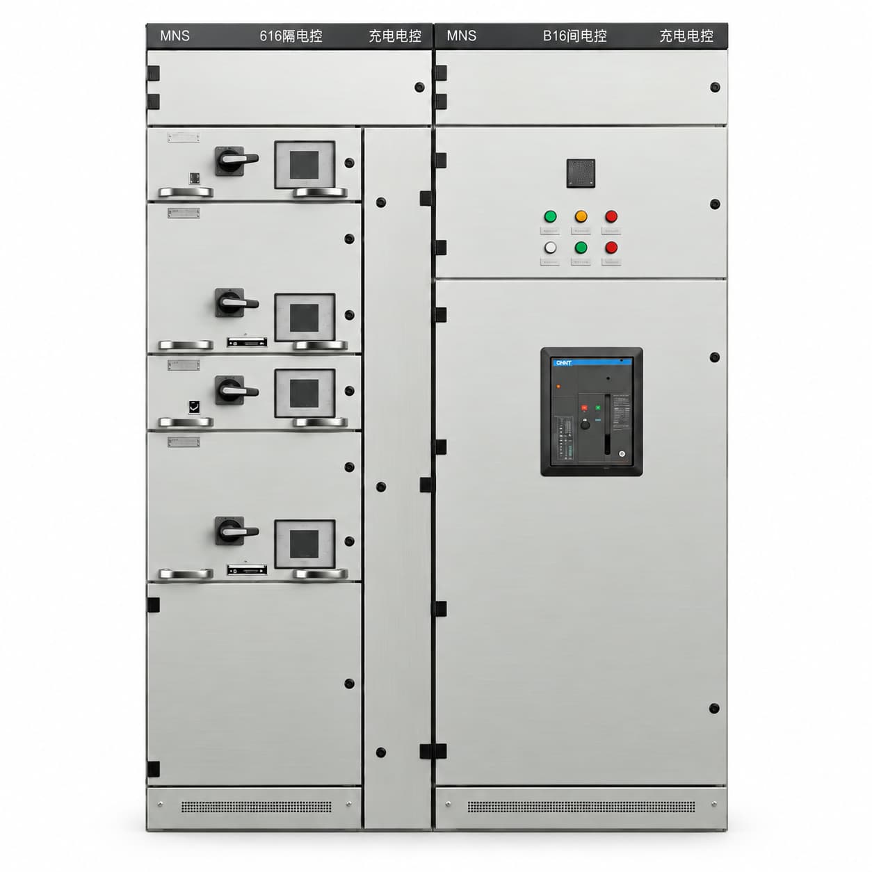
For low-voltage distribution and motor-control systems. The modular cabinet structure accommodates project-defined incoming, feeder, bus-coupler, measurement and control functions, with units, compartments and connection interfaces defined by the scheme.
Order an empty enclosure or assembled equipment. Empty supply includes the agreed frame, functional units and mechanical accessories, excluding internal electrical components. Assembled equipment follows the confirmed electrical drawings.
These uses help assess project suitability; they are not completed project references.
Incoming, feeder, bus-coupler and measurement circuits organized around the factory LV system diagram.
Modular cabinet lineups and wiring interfaces planned around supply needs and installation space.
Functional units and compartments follow the specific system scheme; no redundancy or availability level is assumed.
Control functions follow the motor schedule, with fixed or withdrawable units and interfaces assessed for the project.
These options come from the MNS manual chapter. Fixed or withdrawable units, busbars, interlocks, internal separation and dimensions require assessment of the project scheme; materials, protection and unit forms are not presented as freely interchangeable combinations.
| Item | Listed options / configuration | To confirm for the project |
|---|---|---|
| Working voltage | 220 / 380 / 400 / 415 / 440 / 460 / 480 V | Other voltages are confirmed for the project. |
| Working frequency | 50 / 60 Hz | Other frequencies are confirmed for the project. |
| Installation | Floor-standing; single cabinet / cabinet lineup | Defined by the project layout. |
| Main busbar rated current | Determined by project loads and the distribution scheme | Provide incoming current and load requirements; no fixed current rating is implied. |
| Busbar material | Copper / aluminium | Dimensions and connection methods are project-specific; the materials are not presented as universally interchangeable. |
| Degree of protection | IP30 / IP40 | IP54 and other ratings require project-specific assessment and confirmation. |
| Enclosure steel thickness | 1.5 / 2.0 mm | Other thicknesses are project-specific. Frame, door and mounting-plate thicknesses are specified separately. |
| Enclosure material & finish | Cold-rolled steel / aluminium-zinc-coated steel, selected by part | External finish, other materials and colour are confirmed for the project. |
| Functional units | Fixed / withdrawable | Sizes, quantity and interlocks follow the project scheme. |
| Internal compartments | Busbar, functional-unit and cable areas | Compartment arrangement and form of internal separation are project-specific. |
| Dimensions & cable entry / exit | Width × height × depth, in mm | Dimensions, cabinet lineup and cable interfaces follow the installation drawings. |
Electrical ratings describe the assembled configuration. An empty enclosure alone is not assigned a complete-equipment voltage or current rating.
Final parameters, configuration and scope of supply are subject to the confirmed drawings and order agreement.
Project-defined modular cabinet structure and mechanical parts.
Cabinet structure with the agreed distribution or motor-control circuits.
Define the boundaries for cabinet connections, field cables and interfaces to other systems. Partial supply, onsite installation and commissioning require a separate agreement; accessories, interfaces and included services must be recorded in drawings and lists.
Use the single-line diagram and circuit schedule to define unit forms, internal compartments and installation interfaces.
Use Additional Requirements for the supply form, functional units, outgoing circuit and motor schedules, separation and interface requirements. Attach system and installation drawings after preparing the email draft.
Request an MNS QuoteIncoming, assembly and outgoing checks follow the confirmed product configuration and order scope.
Required documents, submission stages and any witness or special inspection requirements are agreed before the order.
No. The manual lists fixed and withdrawable functional units. Forms, sizes, quantity and interlocks follow the project scheme; arbitrary mixed combinations are not assumed to be feasible.
No. MNS describes a structural series, while MCC describes a motor-control function. MNS-type cabinets may provide motor control when the configuration is confirmed against the motor schedule and interfaces.
No. The listed protection options are IP30 / IP40. IP54 and other ratings require assessment of the enclosure structure, interfaces and project requirements.
Select Request an MNS Quote to open the form with MNS preselected. Enter incoming current, circuit and unit requirements, prepare the draft, attach the system diagram and review before sending.
Final parameters, configuration and scope of supply are subject to the confirmed drawings and order agreement.