

Residential buildings
Final circuits arranged around lighting, sockets and small loads.
Final Distribution · DIN-Rail Modular Devices
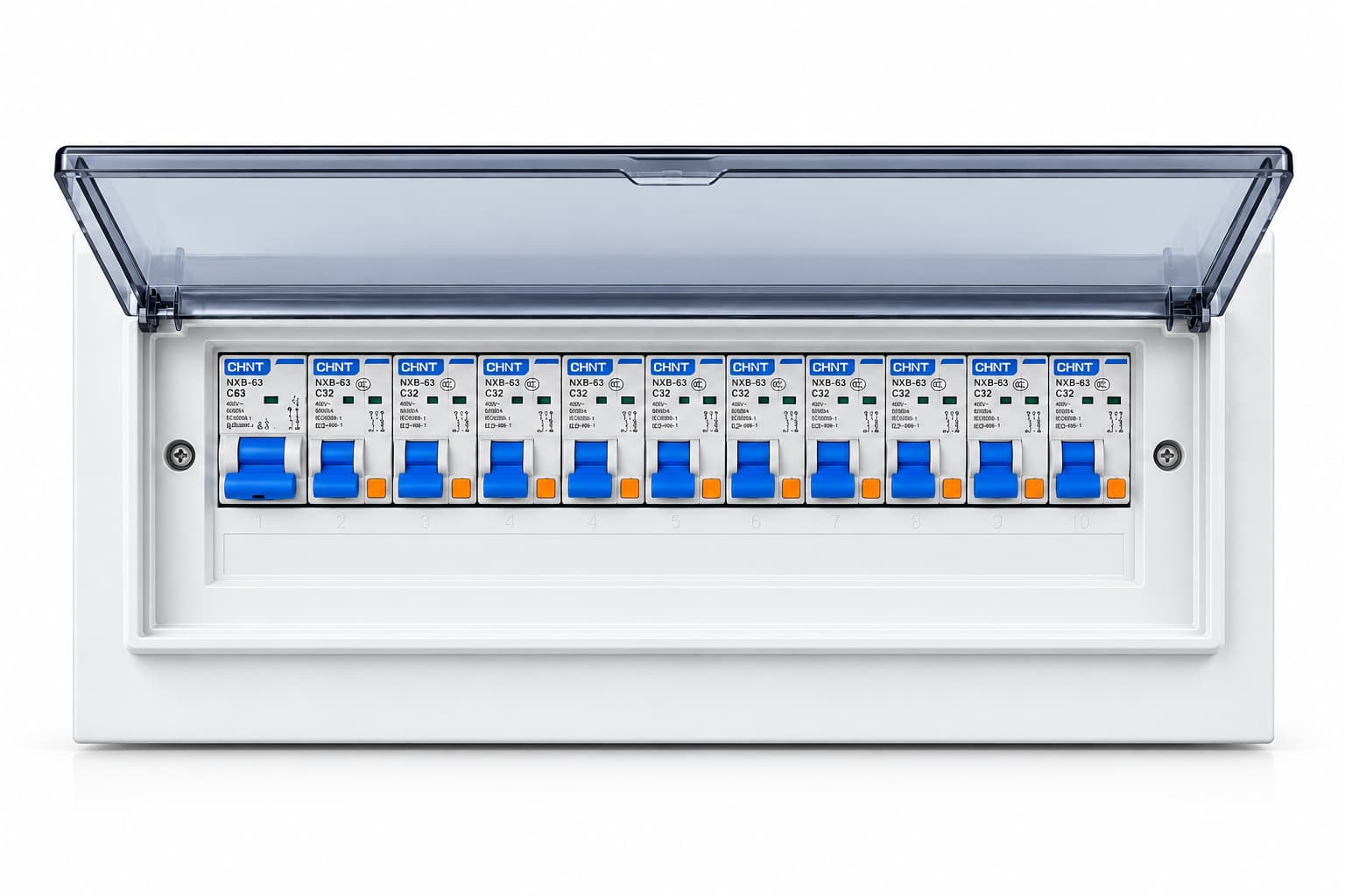
For final distribution to lighting, sockets and small loads, using DIN-rail modular devices. Incoming supply, branch protection and auxiliary functions follow the electrical scheme; module spaces and actual circuit count are confirmed separately.
Choose empty or assembled supply. The enclosure, cover, DIN rails, N/PE terminals and accessories supplied with an empty box follow the agreed list; not all items are included by default. Assembled devices, terminals and internal wiring follow the confirmed drawings and configuration list.
These uses help assess suitability; they are not completed project references.
Final circuits arranged around lighting, sockets and small loads.
Modular devices arranged to office-area loads and the protection scheme.
Surface or flush mounting selected to location, circuits and enclosure space.
Final supply for lighting, sockets and small equipment, with incoming and protection configuration checked against loads.
Options follow manual pages 16–17. Incoming current, module spaces, rows and device layout require project confirmation; the listed upper limits are not guaranteed for every enclosure or combination.
| Item | Listed options / configuration | To confirm for the project |
|---|---|---|
| Operating voltage | AC 220 / 230 / 380 / 400 V | Other voltages are project-specific. |
| Operating frequency | 50 / 60 Hz | Other frequencies are project-specific. |
| Distribution arrangement | Single-phase / three-phase | Phase arrangement, wiring and earthing system are confirmed for the project. |
| Installation | Surface-mounted / flush-mounted | Confirm site conditions; flush mounting also requires recess opening dimensions. |
| Rated incoming current | Not exceeding 100 A | Confirm against loads and the specific configuration; other configurations require separate assessment. |
| Module spaces | 4 / 6 / 8 / 10 / 12 / 15 / 18 / 20 / 24 / 30 / 36 spaces | Other sizes are project-specific. Module spaces are not circuit count: 36 spaces do not mean a fixed 36 circuits. |
| Row arrangement | Single / double / multiple rows | Confirmed against module spaces and device layout. |
| Degree of protection | IP30 / IP40 | Other protection ratings require separate assessment and confirmation. |
| Metal enclosure thickness | 1.0 / 1.2 mm | Other thicknesses are project-specific; panel thickness is confirmed separately. These values do not apply to plastic versions. |
| Enclosure material | Metal / plastic enclosure | Specific material and cover form are project-specific. |
| Protection & auxiliary devices | Miniature circuit breakers, residual-current protection, surge protection and auxiliary devices | Selected to the electrical scheme; not included by default with an empty enclosure. |
| Internal accessories | DIN rails, N terminals, PE terminals and blanking plates | Follow the configuration list; not all accessories are included by default. |
| Overall dimensions | Width × height × depth, in mm | Defined by devices, wiring and installation space. Specify recess opening dimensions separately for flush mounting. |
| Cable entry / exit | Defined by enclosure construction and wiring needs | Openings and interfaces follow the project drawings. |
Devices may occupy different numbers of module spaces. Determine circuit count and enclosure layout from the actual devices and spare-space needs.
Final parameters, configuration and scope of supply are subject to the confirmed drawings and order agreement.
Mechanical enclosure supply for subsequent assembly by the customer.
Enclosure with the agreed components and internal wiring.
External cables, site installation and commissioning require a separate agreement. Mechanical accessories, operating interfaces and partial-supply inclusions must be identified in the drawings and lists.
Provide loads and installation conditions, then confirm module spaces, actual circuits and device layout.
Use Additional Requirements for module spaces, actual circuits, mounting method and material. After preparing the draft, attach electrical and installation drawings in your email app.
Request a PZ30 QuoteIncoming, assembly and outgoing checks follow the confirmed product configuration and order scope.
Required documents, submission stages and any witness or special inspection requirements are agreed before the order.
No. Module spaces describe device installation space. Actual circuit count depends on device widths, protection scheme and spare space.
The manual lists incoming current not exceeding 100 A. Loads, devices and enclosure configuration still require confirmation; other configurations need separate assessment.
No. These values apply only to metal enclosures, with panel thickness confirmed separately. Plastic material and cover form are project-specific.
Not by default. Enclosure, cover, rails, N/PE terminals and accessories follow the agreed list; assembled devices and wiring follow the drawings and configuration list.
The quote button preselects PZ30. Enter circuits, module spaces and mounting needs, prepare the draft, then attach drawings and review in your email app before sending. Flush mounting also needs recess opening dimensions.
Final parameters, configuration and scope of supply are subject to the confirmed drawings and order agreement.